Install three-phase energy meter D103
The D103 can be installed in an electrical panel on a DIN rail or on a wall using the DIN rail strip that is supplied in the kit.
The device should be connected to the power grid by trained personnel with a minimum of group III approval for electrical safety when working on installations up to 1000 V.
To connect the device, follow these steps:
- Connect the current transformer wires to the device in accordance with the wiring diagram.
- Slide the current transformer on the phase conductor.
The transformer has an energy direction indicator, from the electricity meter towards the consumers. - Connect the phase and neutral wires to the device in accordance with the wiring diagram.
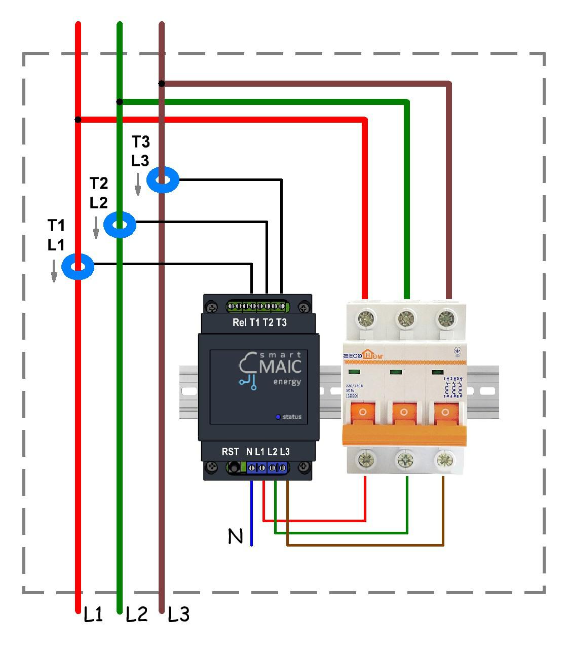
General connection diagram
Connection diagram for rings 100A current transformers
and Rogowski coils 1000A . . 2000A
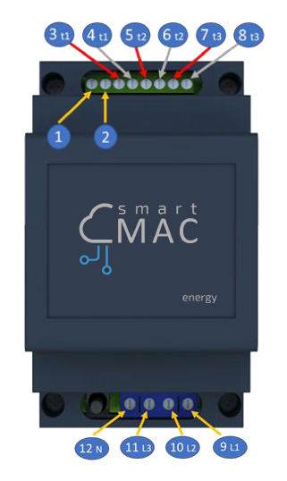
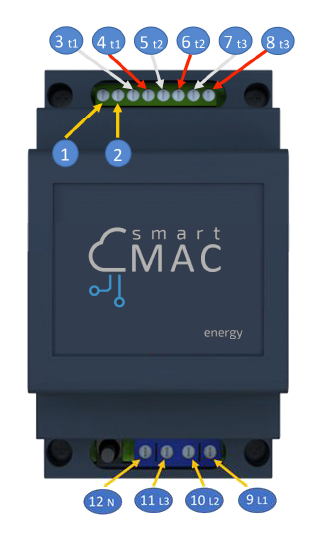
Top group of contacts
1 - controlled output
2 - controlled output
3 - current transformer №1, red wire
4 -current transformer №1, black wire
5 - current transformer №2, red wire
6 -current transformer №2, black wire
7 - current transformer №3, red wire
8 -current transformer №3, black wire
Bottom group of contacts
9 - phase 1
10 - phase 2
11 - phase 3
12 - zero
WARNING :
Incorrect wiring of the phase wire may damage the device.
Connection diagram for clips 300A/600A current transformers
Top group of contacts
1 - controlled output
2 - controlled output
3 - current transformer №1, white wire
4 -current transformer №1, black wire
5 - current transformer №2, white wire
6 -current transformer №2, black wire
7 - current transformer №3, white wire
8 -current transformer №3, black wire
Bottom group of contacts
9 - phase 1
10 - phase 2
11 - phase 3
12 - zero
Also see the extended article on connecting the D103 energy monitor.
Successful measurements!
Customer support service by UserEcho
