D105: Monitoring Deye inverter via RS485 Modbus
Features:
- Connection to the Deye inverter via RS485 Modbus
- Network connection – WiFi
- Data update rate: 5 seconds
- Data transfer and visualization
- Cloud dashboard
- MQTT
- Integration with Home Assistant
Connected to a Deye inverter, smart-MAIC D105 universal meter reads data from inverter's registers via the Modbus protocol. User determines which data to read. Inverter's registers are described in inverter's Modbus RTU Protocol documentation. Data reading frequency is up to 5 seconds. A maximum of 9 registers can be read.
Data received from inverter is transferred to a cloud database and is available for visualization on the smart-MAIC dashboard using graphs and widgets. Alternatively, data can be sent to an MQTT broker. Simple integration with the Home Assistant system is supported.
Using smart-MAIC E2 relay module, you can set up simple automation based on data received from inverter.
Connection and setup.
The D105 device can be located in the inverter's connection bay.
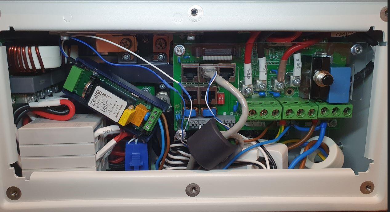
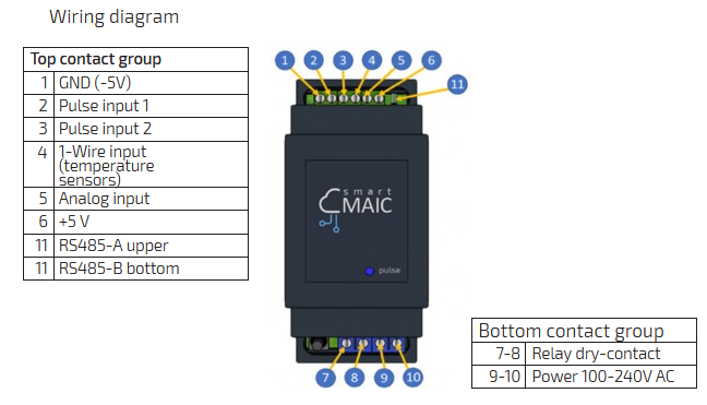
Connect the D105 device to the RS485 interface via the upper A and bottom B pins.
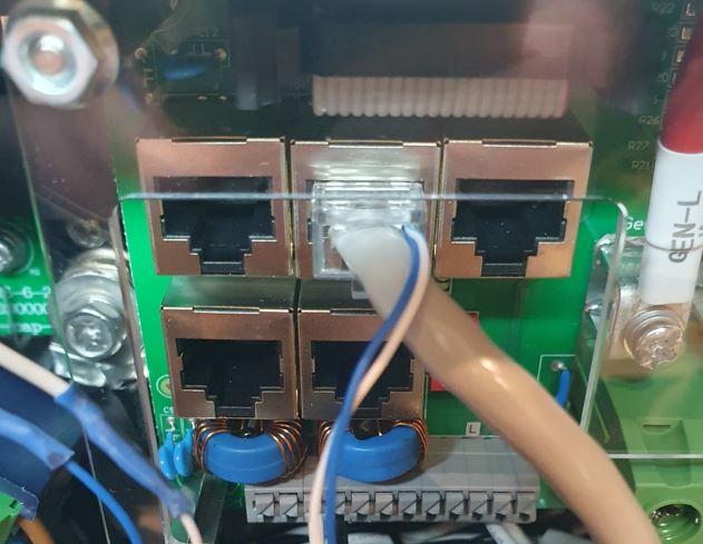
Connect the Deye inverter to the RS485 A and RS485 B inputs via an RJ45 connector.
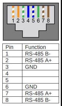
For the RJ45 connector pinout, refer to your inverter's manual. Below is an example for the Deye SUN-6K hybrid single-phase inverter.
Connecting smart-MAIC D105 universal meter to a WiFi network is described in the instructions
https://smart-maic.com/manual/d105.html#
On the D105 WEB interface, it is necessary to configure work with Modbus by specifying which inverter registers to read.
You should have the Modbus protocol description specific to your inverter. Below is an example for the Deye SUN-6K hybrid single-phase inverter.
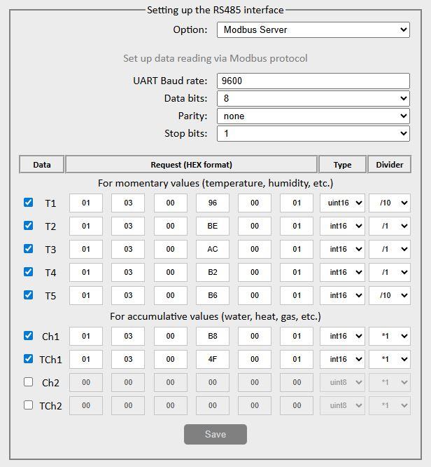
Example 1 - settings for inverter operating with batteries with BMS
d.T1 - (96) [V] grid, network voltage
d.T2 - (BE) [W] battery, charge (negative)/discharge (positive) power
d.T3 - (AC) [W] Grid external Total Power
d.T4 - (B2) [W] load side Total power
d.T5 - (B6) battery temperature -1000
Ch1 - (B8) [%] battery SOC % charge
TCh1 - (4F) [Hz] grid, network frequency
CH2 -
TCh2 -
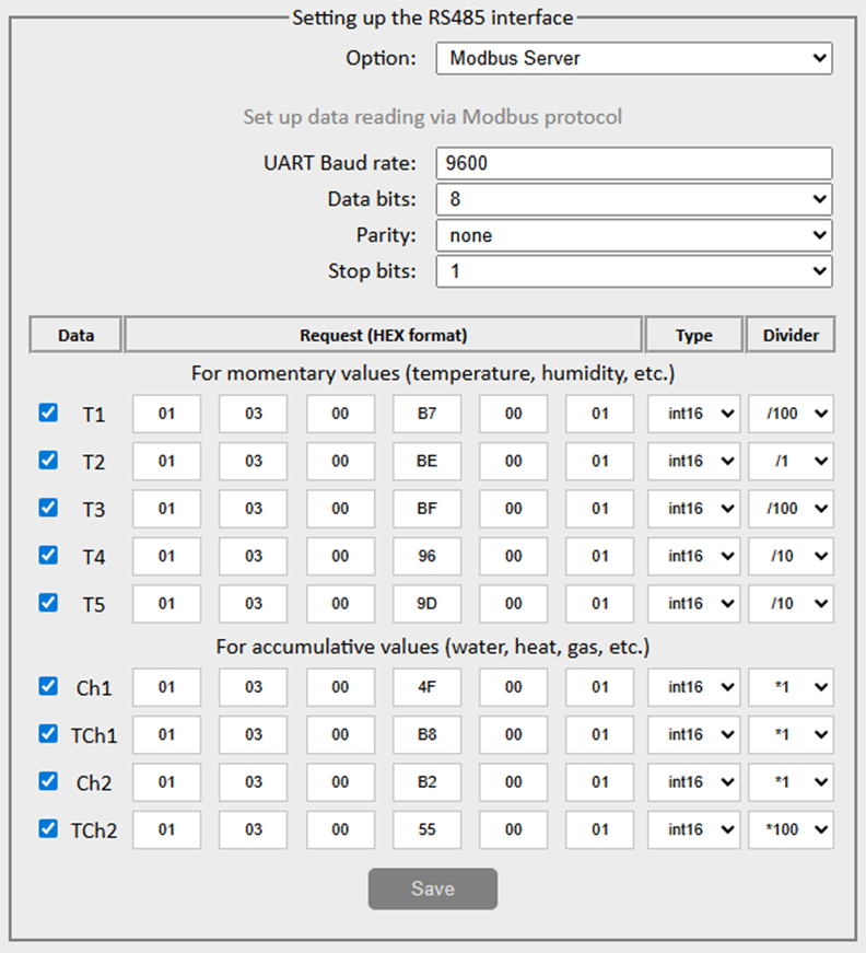
Example 2 - settings for inverter operating with batteries without BMS
d.T1 - (B7) [V] Battery Voltage
d.T2 - (BE) [W] Battery, Power Charge (Negative)/Discharge (Positive)
d.T3 - (BF) [A] Battery, Current Charge (Negative)/Discharge (Positive)
d.T4 - (96) [V] Grid, Network Voltage
d.T5 - (9D) [V] Load, Voltage
Ch1 - (4F) Grid, Network Frequency (/100 on Dashboard)
TCh1 - (B8) [%] Battery, Capacity, SOC
CH2 - (B2) [W] Load, Power
TCh2 - (55) [Wh] Load, Energy Storage Meter
Be sure to check all data in the D105 device's web interface in the "Current Data" menu.
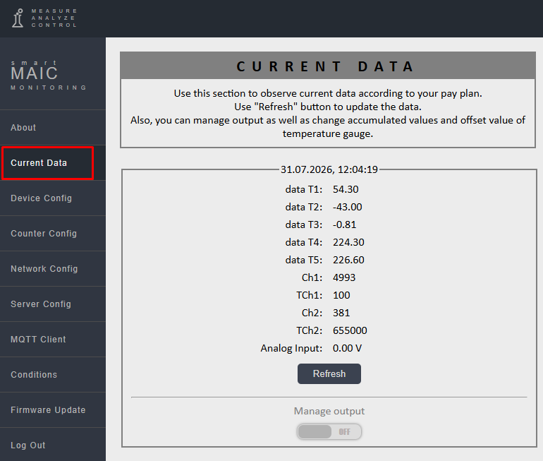
Analyze each digit. If everything is correct, you can proceed to configuring widgets on the Dashboard.
For information on working with the Dashboard, see the Knowledge Base.
https://support.smart-maic.com/en/knowledge-bases/2-main/categories/8-dashboard-and-server/articles
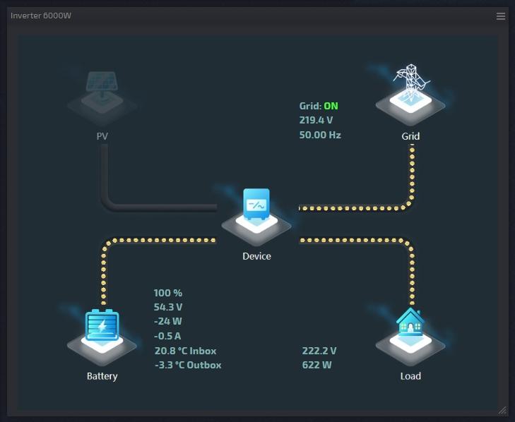
More details on configuring D105 Modbus Sever mode can be found in the article
https://support.smart-maic.com/en/knowledge-bases/2/articles/1038-d105-in-modbus-server-mode
Customer support service by UserEcho