Advanced installation of Energy meter D103
smart-MAIC D103 connection in 3 phase grid
The smart-MAIC D103 energy monitor is designed for 3-phase WYE (star) grid with neutral and uses external current transformers (CTs).
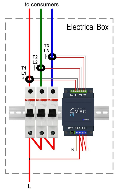
Connect current transformers to the device at inputs T1, T2, T3 in accordance with the figure in the installation instructions. Each current transformer is marked with its number and current measurement arrow. Install current transformers on the phase wires by placing the arrow in the direction of the consumer. Center the current transformers so that they are perpendicular to the wires. This orientation provides more accurate measurement results.
Do not install current transformers on two-wire wires through which zeros and phase are connected at the same time, with this connection the measurement result will be 0.
Connect power to inputs N, L1, L2 and L3 of the device. It is important that the power supply matches the line on which the current transformer is installed.
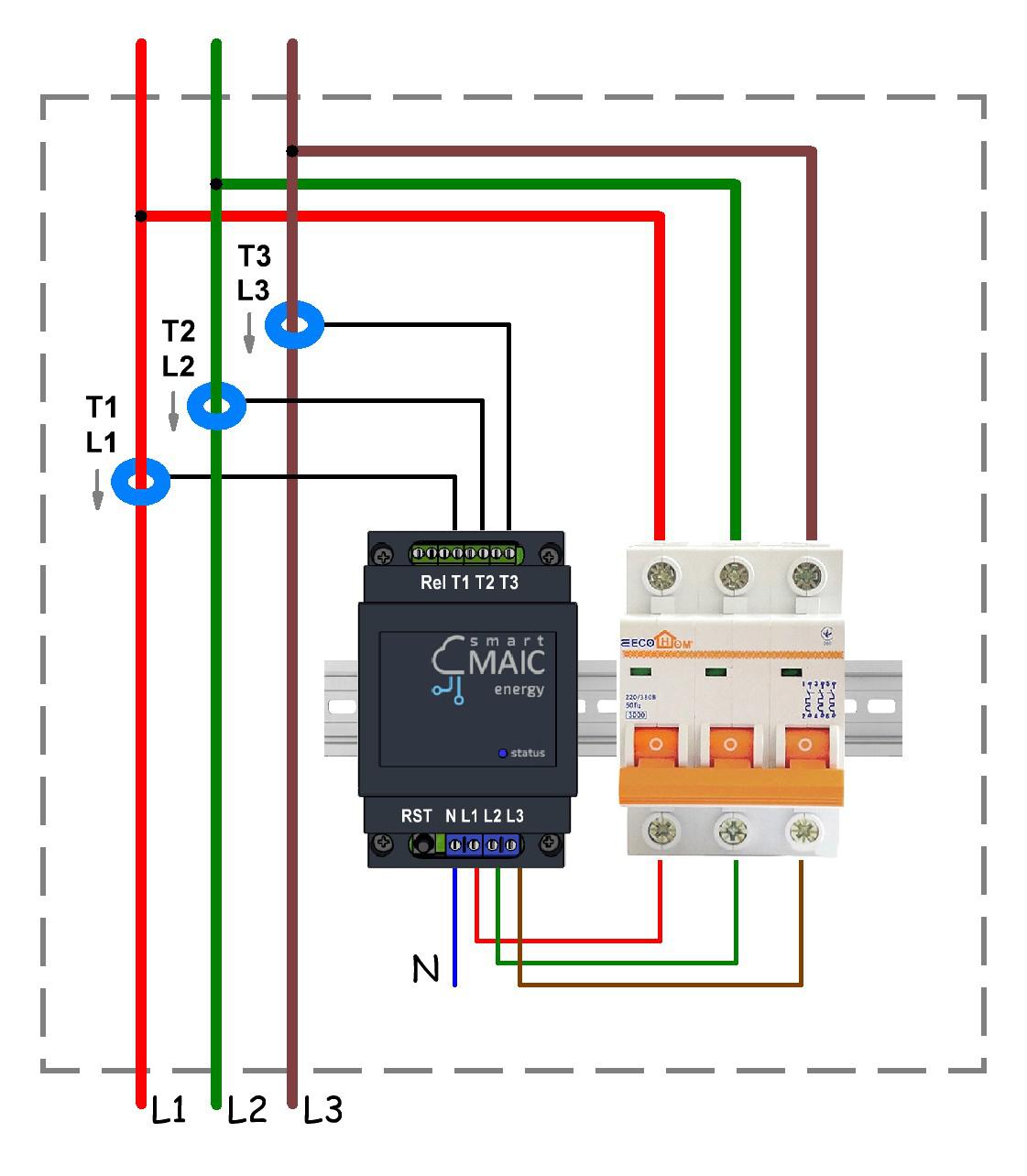
*) Automatic switch of any rating for short circuit protection and ease of installation.
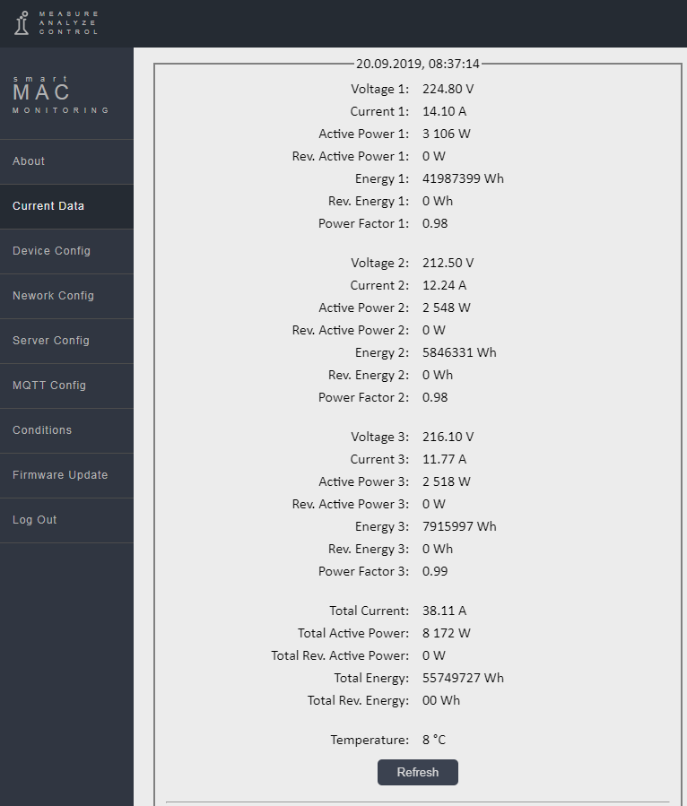
After connecting, щзут the device’s Web page in the “Current Data” menu and check the correctness of the readings taken. Check each number, see if the Power Factor [PF] parameter confuses you (usually aim for 1.00) and if reverse appears when it shouldn’t.
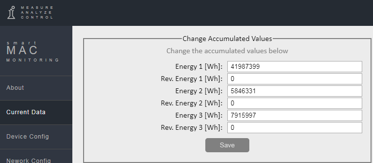
To synchronize the accumulative counter [Wh] and [rWh] with the readings of your electric meter, set the initial values for the accumulative data in the device settings in the Data section. Please note that data is entered in watts.
Measured data
It is important to understand how the data from the smart-MAIC energy monitor is stored at different time intervals. It is especially important to understand the calculation principle for the [W]-Power parameter when it contains electrical power [Watt] or electrical energy [Watt*hour].
| D103 Energy meter measured data, Designation | Real-Time and Minute interval | Hourly, Daily, Weekly, Monthly, Annual interval |
| Voltage, V1 V2 V3 | Voltage in [V] | The arithmetic mean in [V] |
| Current, А1 A2 A3 and TA (total) | Current in [A] | The arithmetic mean in [A] |
| Power, W1 W2 W3 и TW (total) | Instant Active Power [W] | Active Energy for the period [Wh] |
| Reverse Power, rW1 rW2 rW3 and TrW (total) | Instant reverse Active Power [W] | Reverse Active Energy for the period [Wh] |
| Power Factor, PF1 PF2 PF3 | Power Factor (cosФ) | The arithmetic mean |
| Energy, Wh1 Wh2 Wh3 и TWh (total) | Cumulative electricity meter for Active Energy [Wh] | The same, cumulative electricity meter [Wh] |
| Reverse Energy, rWh1 rWh2 rWh3 and TrWh (total) | Cumulative electricity meter for reverse Active Energy [rWh] | The same, cumulative electricity meter [rWh] |
As already mentioned, there is an arrow on each current transformer. If the arrow is placed towards the consumer, then the monitoring data will be saved as follows:
- active power (consumption) in the [W] Power;
- reverse active power (generation) in the [rW] Revers Power;
- the accumulative meter of consumed energy in [Wh] Energy;
- accumulative counter of reverse energy in [rWh] Energy.
Voltage and current must be measured from one phase, check this carefully.
Advice on how to check the connection of D103.
1. Take a multimeter for 600V AC.
2. Make sure that transformer #1 is connected to the input T1.
3. Check that the wires from the transformer are connected by colors correctly, according to the manual.
4. Make sure that the arrow on the transformer is directed towards the consumer.
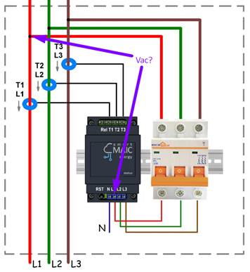
5. Set one probe of the multimeter to the terminal of the L1 device.
6. Set the second probe to the terminal of the fuse next to transformer #1.
7. If the voltage is 0V, then this is one phase, if the voltage is 380V, then these are different phases and need to be corrected.
Repeat this procedure for other transformers.
D103 single-phase connection
Actually, the D103 energy monitor is 3-line. Therefore, it can be installed in a single-phase power for monitoring lines to different consumers (boiler, air conditioning, kitchen, sockets, lighting, etc.)
The circuit is simple. Connect power to one of the inputs and set jumpers for the remaining power inputs L1 L2 L3.
Connect current transformers and put on the appropriate lines that go to consumers.
Reactive Power and Linear Voltage.
For monitoring Reactive Power and Reactive Energy, as well as for monitoring Line Voltage, you can use the calculated values on the widget settings.
See the corresponding article in the Knowledge Base for more details. View »
Have a good measurement!
Customer support service by UserEcho

